Problem 1 - Logic gate output
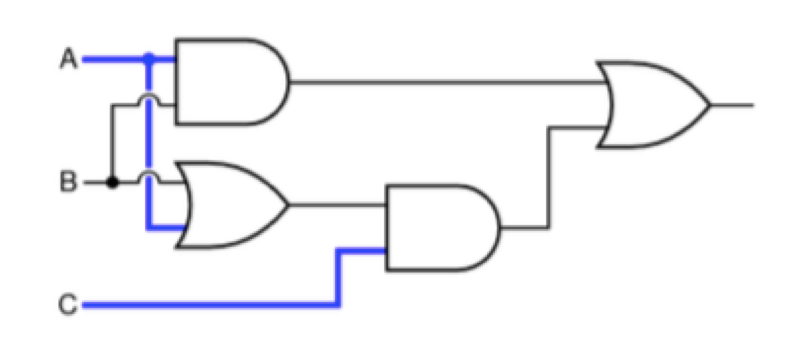
Given the following logic circuit, will the light bulb be on or off if A is a logic 1 (on), B is a logic 0 (off), and C is a logic 1 (on)?
Problem 2 - From Karnaugh Map to Logic Circuit
You are given the truth table for a 3-input Boolean function F(A, B, C):
| A | B | C | F |
|---|---|---|---|
| 0 | 0 | 0 | 0 |
| 0 | 0 | 1 | 1 |
| 0 | 1 | 0 | 1 |
| 0 | 1 | 1 | 0 |
| 1 | 0 | 0 | 1 |
| 1 | 0 | 1 | 1 |
| 1 | 1 | 0 | 0 |
| 1 | 1 | 1 | 1 |
-
Build the Karnaugh Map
- Draw a 3-variable K-map for the function F(A, B, C).
- Fill in the K-map with the output values from the truth table above.
-
Simplify the Boolean Expression
- Use the K-map to group adjacent 1s into valid groups (1, 2, 4, or 8 cells).
- Write the simplified Boolean expression in Sum of Products (SOP) form.
-
Implement the Logic Circuit
- Draw a logic diagram of the simplified expression using AND, OR, and NOT gates.
- Clearly label all inputs and outputs.
-
Implement the circuit using the logic gate simulator from class.
Problem 3
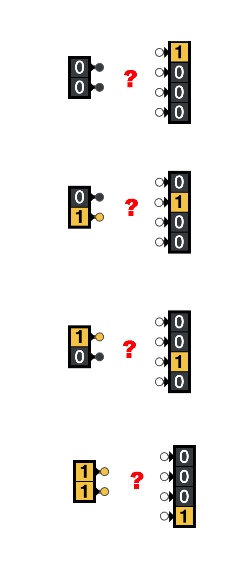
For this problem, please create a “2 to 4 line decoder,” using the logic gate simulator. A 2 to 4 line decoder takes a 2-bit input (e.g., 00, 01, 10, or 11) and has four outputs, one for each of the possible input states.
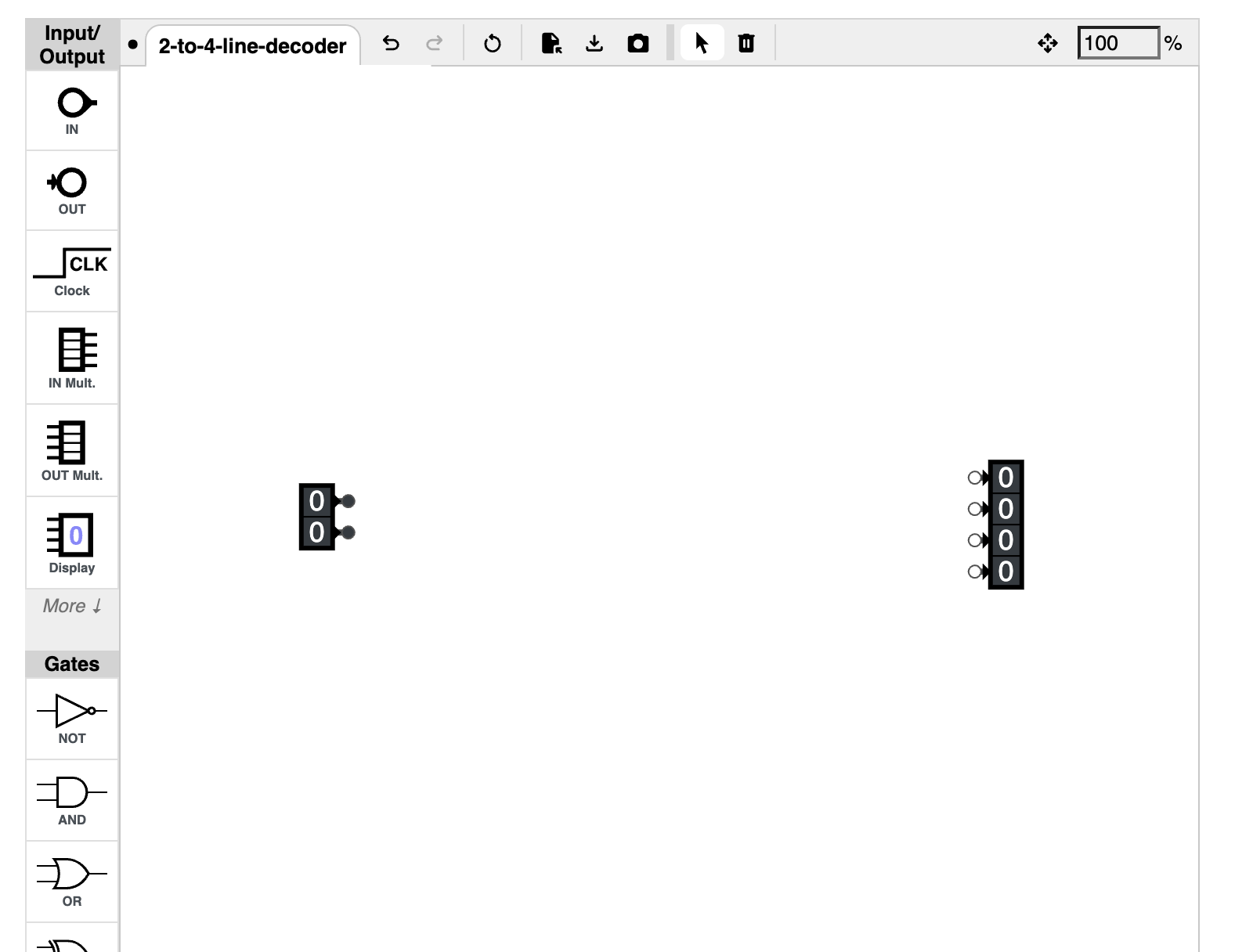
Here is the starter circuit that you can download and then load into the logic gate simulator:
{ // JSON5
  v: 6,
  opts: {name: '2-to-4-line-decoder'},
  components: {
    in0: {type: 'in', pos: [90, 825], id: [1, 2], bits: 2},
    out0: {type: 'out', pos: [530, 830], id: '4-7', bits: 4},
  }
}
This is what the starter circuit looks like. If you want to create a 2-bit input, and a 4-bit output, you can ctrl-click on a regular input or output and select the number of bits:
The following shows the expected output for each of the four inputs: